| LATEST NEWS |
LARGE EDITION PRINTS |
16" EDITION PRINTS |
FOOTBALLER PRINTS |
TRIPLE IMAGE PRINTS |
NAMEPLATE PRINTS |
| PRINT DETAILS & ORDERING | CUSTOMER REVIEWS | THE ARTIST | PRE |
CONTACT DETAILS |
PRE 1825 LOCOMOTIVES
PART 4
Part 1: 1802 – 1808
The Locomotives of Richard Trevithick
Part 2: 1812 –1813
Matthew Murray and John Blenkinsop – The rack railways of Middleton Colliery and Kenton & Coxlodge. Chapman's Chain Locomotives
Part 3: 1813 – 1814
William Hedley – The locomotives of Wylam Colliery
Part 4: 1814 – 1816
George Stephenson (1) – The locomotives of Killingworth Colliery from 1814. Chapman/Buddle locomotives for Wallsend and Whitehaven.
Part 5: 1817 – 1825
George Stephenson (2) – The locomotives of Kilmarnock & Troon, Hetton Colliery and 'Locomotion'. Further Chapman/Buddle locomotives.
1814
George Stephenson – Killingworth Colliery
Geared Locomotive My Lord and Blucher
In 1803, when aged 22, George Stephenson was appointed as the Superintendent Engineer at Killingworth Colliery which was part of the Grand Alliance Company (the company had been formed to protect the mining interests of powerful owners around Durham). In 1813 his responsibility was extended to cover all of the ‘Grand Allies’ collieries.
Stephenson persuaded Sir Thomas Liddle, later Lord Ravensworth, that the colliery would benefit from the use of steam locomotives and in 1814 he was allowed to construct his first locomotive. It had two cylinders 8 inches in diameter with a stroke of 24 inches. The boiler was 34 inches in diameter and 8 feet long with a single fire tube of 20 inches diameter passing through it. This gave less heating surface than a return flue but was cheaper and easier to construct. The cylinders were placed vertically along the centreline of the boiler like Blenkinsop's locomotives. The exhaust steam was released straight to the atmosphere.
The pistons drove cross beams that worked the connecting rods and these operated cranks, which drove the wheels via gears as on Hedley's locomotives. The cross beams were held in place by guides attached to the top of the cylinders and braced to keep them in position. This ensured the piston was kept in a vertical alignment. The locomotive was placed on four flanged wheels without springs. To begin with grooved rims were fitteded to the rear driving wheels and the front wheels of the wagon carrying the coal and water, and were connected together by an endless chain with the idea of improving traction.
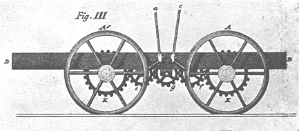 |
| Drawing showing the gear drive of George Stephenson's first locomotive. Taken from Wood's Treatise on Rail Roads 1825. |
The locomotive was tried on the Killingworth Colliery Railway on 27th July 1814 where it was placed on a section of edge rail and ascended a slope of 1 in 450 pulling eight loaded wagons weighing around 30 tons at a speed of four miles an hour. The use of two cylinders gave a smooth motion, remedying the problems caused by using a single cylinder and flywheel. The locomotive went into service at the colliery and it was soon discovered that it did not need the grooved rims on the wheels to carry out its work.
The drive through cranks and gears gave a lot of problems, especially when they became worn, causing jerkiness and a great deal of noise.
This was the first locomotive to use smooth flanged wheels with an edge rail and showed that sufficient adhesion could be obtained using this method, even though it gave less friction than using a flanged plate rail where contact was made with the side of the wheel as well as the rim.
This locomotive was named My Lord after one of the partners, Lord Strathmore. It is possible that another geared locomotive was constructed later in the year, and possible named Blucher. In the local Northumbrian dialect, a bloacher, pronounced 'blucher' or 'blutcher', was used to describe a large beast, or a large unwieldy tool!
1814
William Brunton – Newbottle Mechanical Traveller
After the success of experimental mechanical traveller locomotive on the Crich tramway Brunton had built at his own expense another ‘horse engine’, which was heavier at five tons and probably had two cylinders. The cost was also twice that of the Crich locomotive at £540. This locomotive was sent to the Newbottle Colliery, Wearside, where Thomas Grice assembled it in October 1814. It worked for the rest of 1814 and 1815 achieving a rate of 2.5 miles per hour and climbing a gradient of 1 in 36.
The Engine received a new larger boiler after it was shown that restricting the locomotive to 5 tons was unnecessary and the extra weight would help prevent the locomotive from being lifted off the rails when in operation. Unfortunately on July 31st, it’s first outing with the new boiler, it blew up while surrounded by a large crowd who had come to see the locomotive in action. The boiler was overloaded by the driver through over enthusiasm. The explosion killed a dozen people and injuring several others. This was the first major railway disaster. The locomotive was never repaired as it had become obvious that it was not a practical solution to the adhesion problem.
1815
George Stephenson / Ralph Dodds – Killingworth Colliery
Direct Drive Locomotive
To overcome the problem of using gear wheels to transmit the drive to the locomotive wheels George Stephenson together with Ralph Dodds, who was the Viewer at Killingworth Colliery, took out a patent for a method of driving the wheels using pins attached to the spokes to act as cranks (28th February 1815). The lower end of the driving rod was connected to the pin using a ball and socket joint.
 |
| Drawing showing Dodds and Stephenson's patent for direct drive and coupled wheels to ensure the cranks were kept 90 degrees apart. |
The patent showed two methods of keeping the wheels at the same angle to each other. The first involved using cranked axles with rods connecting them. This was too advanced for the technology of the time as a cranked axle could not be made that would stand up to the constant jarring and forces applied to it in normal working conditions. The second way involved mounting a toothed wheel at the centre of each axle connected by an endless chain.
A locomotive similar in design to the geared locomotives but incorporating direct drive was constructed at Killingworth and tried on 6th March 1815. It worked well and was set to work.
1815
William Chapman / John Buddle – Wallsend, Washington
and Hetton Locomotive Steam Elephant
William Chapman designed a further locomotive with John Buddle who was by this time manager and viewer for the Wallsend Colliery at Newcastle upon Tyne. This was to a more orthodox design consisting of the now normal practice of having two cylinders positioned along, and let into, the boiler. These were 9 inches by 24 inches in diameter and were fitted with slide valves. The pistons drove crossbeams with connecting rods connected to cranks on each side, these drove through reduction gears, with a ratio of 2:1, to the three axles. This would give a top speed of about 4 to 4.5 mph. Adjustments were made by means of the tentering gear, fitted to maintain perfect meshing of the gears and so reduce the grinding associated with this form of drive. The parts for this locomotive were manufactured by Hawks of Gateshead.
The water for the boiler was pre-heated before it was pumped into the boiler in a jacket placed around the bottom of the chimney. Doing this not only saved fuel but also stopped the problems caused by pumping cold water straight into a hot boiler. The exhaust steam was emitted up the chimney.
 |
 |
|
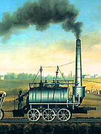
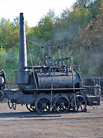
| Part of the painting of the Steam Elephant found in a local school. | The replica Steam Elephant. Photograph © Beamish Open Air Museum. |
This locomotive worked at Wallsend, at this time it was laid with wooden rails which caused problems, so in 1816 it was decided to try it at Washington but the wooden rails used here also caused binding problems so it was laid up. After the Wallsend railway had been relayed with Losh’s patent iron rails the locomotive returned to Wallsend.
The locomotive was rebuilt with a larger boiler and the cylinders were moved above the wheels so direct drive via crankpins on the wheels could be employed. The gears between the frames were retained as a means of coupling the wheels. This rebuilding, which increased the weight from 7.5 tons to 9 tons, could have taken place soon after the locomotive returned to Wallsend. It then seems to have worked for many years and contemporary reports imply that there may have been more than one ‘Steam Elephant’ at work at Wallsend.
After Robert Stephenson, George’s brother not his son, was dismissed from Hetton Colliery he was replaced by Joseph Smith as Company Engineer. Joseph Smith had been responsible for the re-building of the Chapman / Buddle engine at Heaton and also built Buddle’s Rainton locomotive. It seems likely that he bought a Wallsend locomotive to Hetton where it worked for ten years before it disappeared from history. While there it was probably named Fox.
The existence of a Chapman / Buddle locomotive only came to light when a watercolour sketch came to light and was exhibited in 1965. An old lady who had a detailed oil painting based on this watercolour visited the exhibition. Later she gave this to a local school where it remained until retrieved by Beamish Museum in 1995. A piece of text written by Stephen Oliver in 1834 has also come to light ‘The great coalfield of Newcastle appears likely to be exhausted within two hundred years. Shares in railway companies will then be at an awful discount and steam elephants will inevitably perish for want of food!’
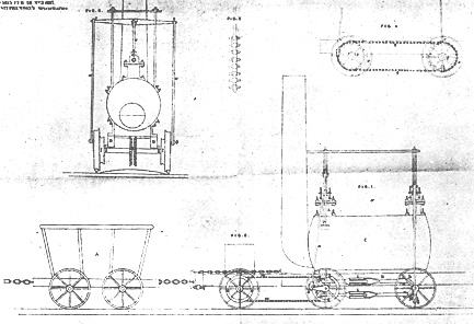
A full-size, working replica of this locomotive has been constructed and can be seem at Beamish Open Air Museum. The staff using contemporary illustrations, the painting, and the original account book for the building of the engine, produced a set of engineering drawings and, in October 1999, started the task of building The Elephant. Much of the construction was done in the North of England, with the final construction and boiler testing taking place at Ross on Wye.
1816
William Chapman / John Buddle – Whitehaven Locomotive
The resident viewer at Whitehaven, John Peile, under the direction of John Buddle, who was a consultant to the colliery, ordered a locomotive from Phineas Crowther to the design of William Chapman. This was a eight wheeled locomotive with the usual layout of having the cylinders in-line and let into the top of the boiler with the drive to the wheels coming from gears on the axles as used on Steam Elephant. It also had a feed water heater mounted on the chimney.
It would appear that this locomotive was not as successful as the Steam Elephant and in 1818 it was converted to a stationary engine at Disington quarry.
1816
John Blenkinsop / Krigar – Chorzow Rack Locomotive
In 1814/5 two Prussian engineers, Eckhardt and Krigar, visited England and saw the Blenkinsop rack locomotives working at Leeds and Newcastle. On his return Krigar, who was the Inspector at the Royal Ironworks in Berlin, set about building a locomotive for the ironworks at Chorzow – then the most important in Europe.
This locomotive was based on the Blenkinsop concept, having two cylinders let into the boiler with the drive transferred from the connecting rods by cranks to gears between the frames. These drove an axle to which was attached a pinion gear positioned on the outside of the locomotive. However it was a lot smaller than the English ones, having a cast iron boiler only 2 metres long with a diameter of 63 cm. The two cylinders were 5.5 inches in diameter with a stroke of a little over 12 inches. This was mounted on a wooden chassis with four wheels. The exhaust steam went to straight to the atmosphere via a separate exhaust pipe, not up the chimney.
The locomotive was finished on 9th July 1816 and the public was admitted to view it for a fee. It was sent to Gliwice where it arrived on 23rd October 1816 there it was discovered that it had been constructed to the gauge used on the underground tramways in the area. This was 1.5 inches narrower than the one used in the ironworks. Trials took place in 1816 but defects were found including leakages from the boiler and cylinders, suggesting poor workmanship.
The trials showed that the locomotive was underpowered and it was decided to fit it with larger cylinders 10.5 inches in diameter. It is not known if this was carried out as it was not put to use on the tramway but converted to a stationary water-pumping engine.
1816
George Stephenson / William Losh – Killingworth Colliery
Steam Suspension Locomotives
The railways on which these early steam locomotives operated were suffering from the weight and forces exerted upon them. So George Stephenson in collaboration with William Losh came up with different ways of fixing and jointing the iron rails to avoid dips occurring. This would enable the track to stand up to the banging and jarring metered out by these heavy machines. The construction of the wheels was changed from cast iron to much stronger wrought iron.
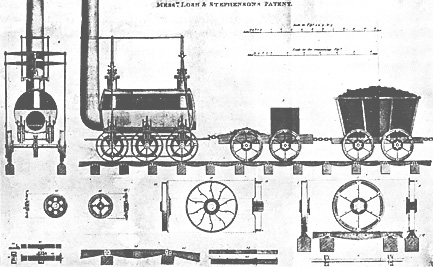 |
| Drawing showing Losh and Stephenson's patent for track wheels and steam suspension. |
The obvious way to make sure the weight of the locomotive was carried evenly between the wheels was to give it some form of suspension. This also had the advantage of ensuring that traction was available from all the driving wheels by making sure they were sitting correctly on the rails. Especially difficult to maintain if six wheels are used. Road vehicles had used springs for a long time but because on these early steam locomotives the drive came from above if the wheels were sprung it would bounce the locomotive. What was needed was a form of suspension that included a form of damper.
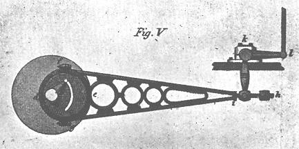
 |
Diagram of the steam suspension system. |
The solution Stephenson and Losh came up with was to place a cylinder on each side of the boiler above each axle; this was connected to the boiler and frame by flanges. The top of each cylinder entered the water space of the boiler and was open at the top to allow the water to enter it. Inside the cylinder was a piston, packed to make it steam tight. A rod, passing through the frame, connected the piston to a bearing that rested on the axle. The axle was held in a guide to make sure it only moved vertically. This enabled the axle to take up any inequalities in the track, providing a relatively smooth running locomotive.
Another change made at this time was the introduction of the eccentric, which had been invented by Nicholas Wood the Viewer at Killingworth Colliery; this was used to operate the valves.
 |
| Wood's eccentric. |
A number of locomotives were constructed incorporating these features and used the usual layout of two cylinders, nine inches in diameter and lined with sheet copper, inserted vertical in the top of the boiler. The pistons worked vertically onto cast iron cross beams which worked connecting rods driving direct onto the wheels.
A valve operated by a handle controlled the amount of steam admitted to the cylinders and so regulated the speed. The steam was admitted alternatively to the top and bottom of the cylinders by sliding valves, which were driven by eccentrics attached to the axles. The exhaust steam was piped into the chimneys, which were turned upwards before they allowed the steam to exit.
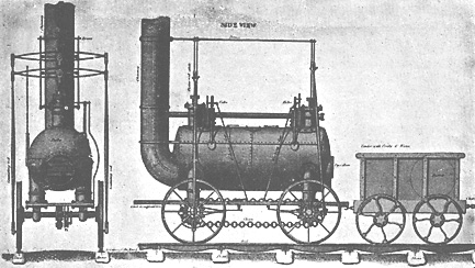 |
| The later Killingworth locomotives with steam suspension, chain coupled wheels and valves operated by excentrics. |
Nicholas Wood in A Practical Treatise on Rail-Roads published a description of the blast pipe in 1825 (an edited version is included below) long before the controversy of ‘who invented the blast pipe’.
‘On the earlier locomotives the steam was exhausted to the atmosphere, this created little noise, but it was found difficult to produce enough steam to keep the locomotive working. Stephenson decided to divert the steam into the chimney through pipes with upturned ends. This increased the velocity of the air through the fire and caused it to burn hotter. The big drawback of this was the noise caused by the escaping steam, which was amplified by the chimney acting like a trumpet.’
When larger flues were fitted to the Killingworth locomotives it was found this level of blast was not required, which led to the locomotives using less coal. The use of a strong blast causes a lot of unburnt fuel to be sucked up the chimney.
Images and text on this site remain the copyright © Richard Green 2003-2026