| LATEST NEWS |
LARGE EDITION PRINTS |
16" EDITION PRINTS |
FOOTBALLER PRINTS |
TRIPLE IMAGE PRINTS |
NAMEPLATE PRINTS |
| PRINT DETAILS & ORDERING | CUSTOMER REVIEWS | THE ARTIST | PRE |
CONTACT DETAILS |
PRE 1825 LOCOMOTIVES
PART 2
Part 1: 1802 – 1808
The Locomotives of Richard Trevithick
Part 2: 1812 –1813
Matthew Murray and John Blenkinsop – The rack railways of Middleton Colliery and Kenton & Coxlodge. Chapman's Chain Locomotives
Part 3: 1813 – 1814
William Hedley – The locomotives of Wylam Colliery
Part 4: 1814 – 1816
George Stephenson (1) – The locomotives of Killingworth Colliery from 1814. Chapman/Buddle locomotives for Wallsend and Whitehaven.
Part 5: 1817 – 1825
George Stephenson (2) – The locomotives of Kilmarnock & Troon, Hetton Colliery and 'Locomotion'. Further Chapman/Buddle locomotives.
1812
Matthew Murray / John Blenkinsop – Middleton Colliery
Rack Locomotives Prince Regent, Salamanca, Lord Wellington (and Marquis Wellington ?)
The Napoleonic War was having a serious effect on the cost of fodder for horses and therefore pushing up the price of haulage. John Blenkinsop the manager of Middleton Colliery, Leeds decided to try using steam locomotives, which used a fuel readily available on site, to haul the coal from the colliery by railway into Leeds. He instructed Matthew Murray (1765-1826) of Fenton, Murray and Wood based in Water Lane, Leeds to construct a locomotive. By this time, Murray's company was challenging Boulton & Watt for the position of the leading producer of steam engines in Britain.
As it was still doubted that sufficient adhesion could be obtained from using smooth wheels on smooth rails to haul a useful load these locomotives were designed with a cogwheel (pinion), which engaged with special rails cast with teeth (rack) along the edge. Also it might have been decided that a rack system would be required as these locomotives were to be made as light as possible, to avoid the problems caused by Trevithick’s locomotives which because of their weight damaged the track and therefore would not been able to haul the loads required just using adhesion.
Another possible reason may have been that Blenkinsop had patented the rack and pinion system (10th April 1811) and persuaded the colliery owners that this was the best system to apply and so make some money from the patent rights! The decision to adopt this system would not have been taken lightly due to the cost of relaying the railway with the special rack rails. Whatever the actual reason it was undoubtedly a success as these locomotives were recorded hauling loads of 90 tons at 4 miles per hour.
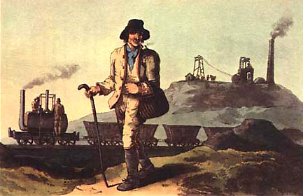 |
| Watercolour by George. Walker, published in 'The Costume of Yorkshire' in 1814, showing Middleton Colliery. |
The first locomotive built appeared in public on 24th June 1812. The boiler was of cast iron, oval in section, working at 55lb. per sq. in. The cylinders are believed to be 9 in diameter with a stoke of 22 in. Subsequent locomotive had the cylinder diameter reduced to 8in. The wheels were 3 ft. diameter and the cog wheels 3ft 2 in. It is thought to have been named Prince Regent.
There seems to have been a formal inauguration of steam traction on 12th August 1812 when a second locomotive was introduced. It was named Salamanca after the battle fought near the Spanish University city on 22nd July 1812 in which the then Earl of Wellington defeated the French Marshal Auguste Marmont.
Two further locomotives were built to work another portion of the railway. The first was named Lord Wellington and was delivered on 4th August 1813. The fourth locomotive was delivered on 23rd November 1814 and seems to have been known as Marquis Wellington. Confusion has arisen over these names and they may have been only popular appellations.
The colliery was visited by Grand Duke Nicholas, later Tsar of Russia, who took a keen interest in the locomotives. The manufacturers later sent him a model.
The locomotives had two vertical cylinders set into the boiler fore-and-aft along the centreline. These drove crosshead beams with connecting rods going down each side of the boiler to cranks on cross-shafts which drove gears between the frames, below the centreline of the boiler, these in-turn drove another cross-shaft connected to the drive cog on the left hand side outside the frame. The cranks for each cylinder were set at 90 degrees to each other, which ensured the locomotive would always start, as at least one cylinder would always be on a power stroke when the engine was stopped. This arrangement of having at least two cylinders set 90 degrees apart became standard for all future locomotives.
The boilers had a single straight-through flue with the exhaust passing to the atmosphere via a silencer and exhaust pipe between the cylinders. This arrangement was later changed with the exhaust steam the steam being ejected up the chimney. The boiler was set on two longitudinal wooden baulks to which were fixed the four carrying wheels and the bearings for the cross-shafts. Even though there was no suspension the use of wooden baulks would have given some flexibility and so avoid some of the jarring and reduced breakages.
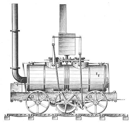 |
| Drawing of Blenkinsop's Rack Locomotive. |
Some contemporary drawings and illustrations of these locomotives show them with cogwheels (pinions) on both sides of the locomotive although the rack was on one side only! It is impossible to have a rack on both sides if you have to negotiate curves. Blenkinsop would have liked to have placed the rack between the rails but had to settle with having them on one side to avoid interfering with the horses, which were still in use. The problem of having the rack on just one side is that the power is not transmitted evenly and must lead to at least the cross shafts and gears twisting under load causing noise and ware. This is why modern versions of the rack and pinion system used nowadays on railways with very steep gradients, have the rack in the centre of the track.
These illustrations are obviously wrong, but it would have been a good idea to construct them this way to enable the locomotives to be turned from time-to-time to even out the wear. The locomotives cost £380 each, which included a royalty of £30 to Trevithick for his patent rights. Trevithick’s influence in the design is evident in the use of cocks to distribute the steam instead of using the more modern slide valves, which had been patented by Matthew Murray (28th June 1802).
Although these locomotives were fairly expensive to use and heavy wear took place between the driving gear wheel and rack they were the first commercially successful steam locomotives produced; four of them had replaced 50 horses and 200 men! They continued to work for many years, the last exploding in 1834. By this time it had been proved that a rack and pinion system was only needed when exceptional gradients were required so the rack system was replaced with standard edge rails.
1813
Matthew Murray / John Blenkinsop – Orrell Colliery,
Three Rack Locomotives
The first locomotive was put into use at Orrell Colliery, Wigan at the beginning of 1813. They were stated to have weighed 6.5 tons and are thought to have been built, by arrangement with Blenkinsop, at the Haigh Foundry.
1813
Matthew Murray / John Blenkinsop – Kenton & Coxlodge
Colliery Rack Locomotives Lord Wellington plus 2 others
The viewer of the Kenton & Coxlodge Colliery wagon-way (Newcastle), John Watson, was a friend of Blenkinsop and he agreed to purchase Lord Wellington from the Middleton Colliery. To operated this type of locomotive the Kenton & Coxlodge had part of its system converted to rack rails. The service was started on 2nd September 1813.
This locomotive was soon joined by two others, which were specially built for the colliery in Tyneside. These were larger than the earlier Middleton ones due to the longer distances and the heavier loads encountered here. The first of these later engines soon needed replacement pistons and gears.
Watson claimed that they worked well but stated that another viewer interfered with the operation of these locomotives using untrained men who mistreated them. This fact combined with the heavy loads and gradients (1 in 24 in parts) meant they became unserviceable and were out of service by the time the colliery was sold in 1817.
1813
William & Edward Chapman – Heaton Chain Locomotive
Horses were generally used to haul the wagons on these early industrial railways, with self acting inclines being used where possible. Stationary steam engines were used when loaded wagons had to be hauled up a steep incline. Haulage on inclines was by means of ropes or chains. William Chapman a leading civil engineer, who was also a keen mechanical engineer and had patented a successful rope-making machine, took the stationary steam engine and chain method of haulage and reversed it. In December 1812 he took out a patent (paid for by John Buddle) for a chain locomotive and bogies.
The Butterley Company of Derbyshire built a six wheel, bogie, chain locomotive. This had a grooved capstan mounted centrally under the boiler. It was completed in August 1813 and sent to Heaton Colliery (Newcastle) where John Buddle was a partner and viewer. It was assembled by Butterley’s fitter, Thomas Grice and was ready for trials by October.
A chain was stretched out along the railway fixed it at both ends. This was then passed once around the capstan under the locomotive and as the capstan rotated it pulled the locomotive along the railway. This turned out to be extremely clumsy but the experiments continued throughout 1814 and into 1815 when disastrous flooding closed the colliery in that May. During this time it is thought that the locomotive was sent to the Lambton waggonway for a demonstration. The locomotive finished its life as a pumping and winding engine.
1813
William & Edward Chapman – Lambton Chain Locomotive
William Chapman had already demonstrated his chain locomotive on the Lambton waggonway and John Buddle, who also happened to be the viewer of the Lambton Colliery, got the agreement of the board to order a locomotive and to convert the whole of the system to iron rails and to lay a chain.
The locomotive was built by Phineas Crowther and was an eight wheel joint chain and adhesion locomotive. The trials dragged on as the waggonway was only converted slowly and in the end the locomotive was laid aside. The waggonway was redesigned to use self-acting inclines and stationary engines.
This locomotive was later sent to Heaton and rebuilt as Heaton II (see later 1820, William Chapman / John Buddle – Heaton Locomotive ‘Heaton II’)
1813
William Brunton – Crich Mechanical Traveller
The question of obtaining enough friction from the driving wheels of a steam locomotive was occupying the minds of many and in May 1813 Brunton patented the idea of using mechanical legs to provide the traction by pushing the locomotive along.
Brunton built a locomotive with mechanical legs at Butterley, Derbyshire, where he was an engineer. The locomotive had a single cylinder, 6 inches in diameter with a stroke of 24 inches, set into the rear of the boiler operating jointed legs giving a step of 26 inches. The pressure was normally 40-45 pounds per square inch and the whole locomotive weighed 2.25 tons. The cost of £240 was charged to Brunton.
 |
| Schematic Drawing of Bruntons Mechanical Traveller. |
The locomotive worked as follows. A horizontal cylinder is connected to one of the legs at the knee. When the piston is driven back, it presses the leg against the ground, and thus propels the engine forward. As the engine advances, the leg straightens and as the limit of the step is reached it causes the arm above to rise; this pulls a cord, which lifts the foot from the ground. The action of the other leg is similar, but the motion is derived from the first leg not the cylinder. A rod attached above the knee of the first leg is connected to a toothed rack. This rotates a cogwheel on the centreline of the boiler, which operates a rack on the other side with a rod from this attached to the second leg. When the piston is driven out and pushes the first leg, the left rack is drawn backward, turning the cogwheel, which pulls the right rack forward, and operates on the second leg in the same way as the piston-rod does on the first one, and thus the legs take alternate steps, and walks the engine forward.
The locomotive was set to work on the plateway that connected the Crich limeworks, owned by the Butterley Company, to the Cromford Canal at Amber Wharf. The plateway was 1.25 miles long with a gradient of 1 in 50 towards the canal. This experimental locomotive worked well but showed some changes needed to be made.
Images and text on this site remain the copyright © Richard Green 2003-2024